
The AN/ARC-174 radio system or commercially known as the 718U-( ) series, has enjoyed very wide scale deployment in a number of applications with a wide range of configurations. While you rarely see it in Ham Radio operations due to the lack of an VFO mode and operatiing at 28 VDC (most ham operators use 12 VDC), a limited number of Ham's have enjoyed its use. We are great fans of this family of HF systems as it is well designed, it was very easy for Collins to have a wide range of system elements to meet any customer requirment, most important, Collins investors got their money's worth in this specific technology solution. They had a well thoughtout design plan and implemented it well.
Warning: Due to a wide range of IF filters possible and which type of user group was using the radio, the FCC type acceptance number can vary for US customers. There is a narrow band version using 2.4 KHz for Upper and lower sideband. There is also a 2.85 KHz version typicalled used by the Military when secure voice or data was used. You can examine the control head for what the radio can do (assuming the internal parts are installed). There was even some users who required a CW option. You need to closely look at the last digits of the receiver-exciter model number and then look at the chart below. This included both aircraft and in several specific "fixed" or land mobile & marine applications. While it is generally possible to swap the 671 Receiver-Exciter between systems, you really need to ensure the 671 model has the filters in it that you need to meet your application.
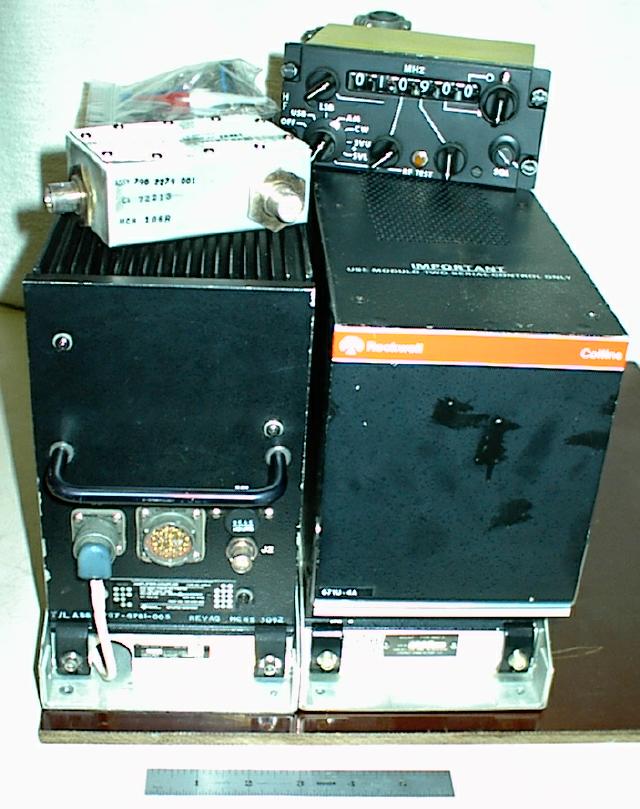
The Military version was known as the AN/ARC-174 and was most commonly installed in military helicopters and some special use aircraft. The AN/ARC-174 was the unpressurized commercial version of the 718U-5 and used the 548S-3 100 Watt amplifier. As far as we can tell, all military units used the 2.85 KHz SSB filters. The pressurized amplifier was the 548S-5 unit.
The system was designed to operated between 2.0 MHz and 29.9999 Mhz for a total of 280,000 channels (100 Hz steps). The system could support a number of operating modes such as SSB (LSB and USB), Secure Voice (SUSB and SLSB) AM, and CW. In addition, various data modes such as secure voice and low speed data service (depending on the bandwidth of the 671 Receiver-Exciter unit used [2.4 or 2.85 Khz]). There were a number of military implemenations that used data at 2400 bps as well as some implementations at 4800 BPS It was possible to use 39 tone and single tone modems (188-114A or B) and ALE operation (1G and 2G) depending on options internally installedi or externally connected. When using ALE, the 309 external ALE module (309L-3 for first generation and the 309M-1 for second generation) was required and a different control unit (514A-13) was used. Output power ranged from 100 watts up to 1 kilowatt with the average installation being about 100 (average or peak). The most common was 100 watt operation for Military and 400 Watt for overwater commercial aircraft operation (you saw a lot of dual Boeing 747 installations at 400 Watts). Or in some limited cases such as the Boeing 747, the 400 watt versions of the amplifier were very popular (those with lots of spare DC power!). In one specific product application, the 671U-4 module was used as the exciter for a Collins 208U-10 10 KW Amplifier and the HF-8022 10 KW Amplifier. There were some unusual vehicle mounted versions also such as the AN/VRC-81 (see below) and the AN/VRC-114 series. There were a number of marine installation with the ALE option (1G) for the US Customs & Border Patrol operations. The input power used was 28 VDC (@25 amps) for the basic 100 watt version. The 400 watt and the 1,000 versions used a variety of primary power options (28 VDC and 115 VAC/400 Hz). The manual says the 400 watt version (using the 548A-1 Power Amplifier and the 636X-1 series power supply at 28 VDC) required a 150 amps which seems a bit crazy. The basic backage weight, as a AN/ARC-174, was 33 lbs or about 14 Kilograms.Note: if using for Data applications, remember to check the duty cycles of the Exciter and PA units. This information can be found in the service manuals.
Note: there is an error on the coupler section of the drawingn. The image will be adjusted soon to show the information from below.
Some of the systems were later upgraded to support a form of selective calling used by the airline transport companies using a four audible tone system. The United States military created the Automatic Link Establishment (ALE) capability. (It should be noted that Collins was one of the key pioneers in this technology.) The original Collins name for their solution was called "Selscan" which was basically ALE 1st Generation. The first generation ALE was primary used by the US Customs and Border Partol organization .The Harris RF organization also was big in the ALE area for the fixed, marine mobile HF community and their solution was called "Autolink". As expected, the systems could not interoperate. This was solved in the 2nd genration of ALE.
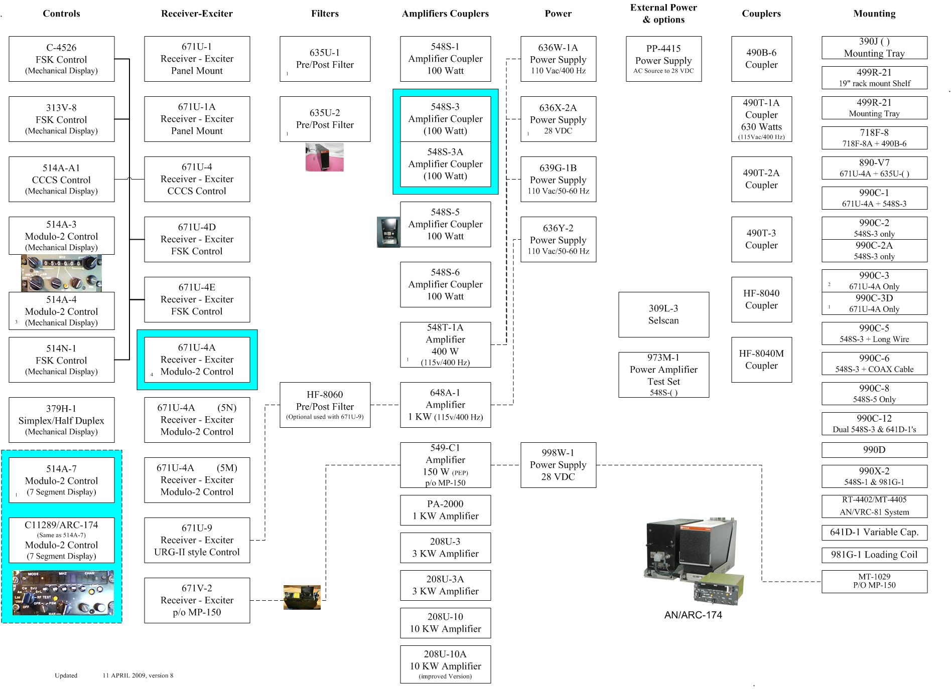
Within ALE 2nd Generation period, it all came together as one US Standard (see our section on ALE). This evolution of the standard was later used by NATO for their HF deployments. The technology has since evolved to become a basic global standard used in all commercial and military applications. The main thing to remember about the 718 series was that it had a very successful life and is still in service in some fashion in nearly all airlines today and is still installed in many military aircraft around the world. It has had perhaps one of the most understated successful products within the Rockwell-Collins communication product lines. It was clearly crossing the gap between the commercial world and the military world. With one minor exception (the 548S-5), the product more or less has remained the same. It is only now, more than two decades later, is the equipment being phased out as the small component parts used to repair them are no longer being made (discrete transistors, etc.) The initial documents of the 718U (6 MB of TIFF 5.0 files) with more to come. The material gathered from the Maintenance document and other sources. An overview of the various variations is here. This radio is being replaced by the AN/ARC-220 series in order to support datalink (HFDL) requirements required by the commercial airline world as a backup to the existing Satellite and VHF based system. There are some images yet to be processed in the main directory under "unsorted" images that may be useful. See here The AN/ARC-174 or 718U family is made up of several key modules. These include:
Systems:
 718U-1		aka AN/TRC-169
 718U-2		aka AN/VRC-80
 718U-2A & 2B	aka AN/VDC-81
 718U-3
 718U-4A	400 Watt Aircraft version (replaces the 618T series)
 718U-5		(the main discussion of this web site)
 718U-9		Special transportable version (various elements from above)

Receiver-Exciters
 671U-1/1AA	Panel Mounted (only seen a photo of this unit but have a partial manual for it)
 671U-4		Special version with CCCS control signallinga (very rare)
 671U-4A	Shelf Mounted - Modulo 2 control and uses 2.85 KHz Receiver filters (generally used by the military)
			  Part Number	787-6934-004
					787-6934-007
 671U-4AN	Shelf Mounted - Modulo 2 control and also has a narrow bandwidth for aircraft (part 87) and marine use (part 83) - 2.4 KGz filters
	                  Part number	622-2631-001
 671U-4B	Shelf Mounted - FSK control
 671U-4D	Shelf Mounted - FSK control
 671U-4E	Shelf Mounted - FSK Control

 671U-10	Shelf Mounted - Unknown control
			  Part Number    622-3270-003

Ampfilier/Antenna Couplers (solid state final - 2.000 to 29.9999 MHz)
	RF Drive to obtain 100 Watts i(after the coupler) is 100 milliwatts
	Harmonic attenuation is at least 50 db below carrier frequency
	Tune time is 3 seconds nominal
	Note: Do not use above 55,000 feet or 16,764 meters (unlikey)

 548S-1   100 Watt - used with front panel system (rare) - mostly for vehicles or backpacks.
                     Can run off the BB-451 Battery. Power required is 28 VDC at 20 watts in receive and 280 watts transmit
 548S-3   100 Watt - Basic Amplifier and Antenna-Coupler (most common version)
 548S-3A  100 Watt - Recent version - Approved for Maritime Use (FCC Part 83)
 548S-5   100 Watt - Pressurized (Also known as the AM-7202/ARC-174)
          	Front View
	  	Side View
          	ID Plate View (Left side)
          	ID Plate View (Right side)
          	Antenna Connector (back) View
		Equipment description (from Service Manual)
 548S-5A  100 Watt - Recent version - Approved for Maritime Use (FCC Part 83)
 548S-6   Unknown

Amplifiers Only (no antenna coupler)
 549C-1	  150 Watt (part of the MP-150)
 548T     400 Watt (tube in Final)
 548T-1A  400 Watt
 648A-1	  1000 Watt (never seen this unit but I do know it exists)

Antenna system
 437R-2   Monopole adapter

Power Supplies (used with the 548T Amplifiers or various system packages)
 636W     Supply (3 phase, 400 Hz)
 636X-1   Supply (28 vdc, 150 Amp?)
 636X-2A  Power Conditioner (28 VDC filter in essence)
 639G-1   Supply (28 vdc, 75 Amp) used with the 718U-2B family
 PP-4415  Supply, AC input, 28 VDC at 50 Amp output

System Control Heads
 514A-3   Modulo 2, Manual control (Mechanical display)
 514A-4   Modulo 2, Manual control (Mechanical display) (various versions depending on lamp voltage)
	  Part Number:
		792-6122-002
		792-6122-003
		792-6122-013 (used in the Boering Aircraft and the faceplate is in Boeing Gray color)
                792-6122-014 (used in the Boering Aircraft and the faceplate is in Boeing Gray color)
 514A-5	  Unknown use - shown in documents - uses 28 VDC wiring
 514A-6	  Unknown use. Saw mentioned as just a foot note.
 514A-7   Modulo 2, Manual and stored programming control (also know as C-11289/ARC-174) (part number 622-4093-001)
	  Please see the wiring notes if using instead of the 514A-4 (detail)
 514A-8   Unknown (Collins Part Number 622-5463-001 to -006, export restricted) Also has another part number of 622-5463-011
 514A-9   Unknown radio (Collins Part number 622-5690-001) but is much later than the A-7 head.
 514A-10  Unknown
 514A-11  Unknown
 514A-12  Used with the 671U-4A and the Selscan 309L-2 controller (1st generation ALE)
 514A-13  Unknown use - might be for the 2G ALE (309M series) controller

 313V-7A  FSK Control Unit
 313V-8   FSK control only
 373Q-2	  Secure Voice Remote Control (used with the VP-110 Secure Voice Module)
 379H-1   Used to control dual 718 systems to provide "split channel" operation
 514N-1   FSK Control only
 C-4526   FSK Control only, Vehicle mount or remote mount for field applications

Test Sets
 973L-1A  Receiver-Exciter test set

Antenna Couplers

 490B-4	  Vehicle unit
 490B-6   Vehicle Unit

 490M-20  Marine use

 490S-1   Antenna Coupler - see the description

 490T-1   Used with the 618 and the 400 Watt 718 series. AKA CU-1669A system. Supports 630 Watts and requires 115 VAC, 400 hz
 490T-1A  Used with the 618 series. AKA CU-1669A system. Supports 630 Watts and requires 115 VAC, 400 hz. See: http://f1frv.free.fr/main3p_490T-1.html
 490T-2   Used with high power systems
 490T-2A
 490T-3   Used with high power systems such as the URG-II series and not the 718 Series
	  Rated at 1.2 KW average or peak. Required single phase 400 Hz 115 VAC
 490T-4	  Rated 1.2 KW Average or peak. Used as a line flattner
 490T-8	  Similar to the 490T-3 but is 28 VDC powered.
 490T-9   Used mostly with the 618T-2 series, Part number 522-4994-001, 115 VAC/400 HZ power requirement

Mounting trays or cases
 890V-7	  Used to mount the 671( ) and a 635U-2. This tray is part of the 499R shelf system.
	  Note - the connector types are similar in appearance to the 990C but the functions are very different.
                 They are not interchangeable! You need to make special cables to use the shelf and either a 548S-3 or a 548S-5 PA unit.
                 The power for the 548S-3 and the 548S-5 use a different pin ("W" for the 548S3 and "r" for the 548S-5)
                 The PA Interface connector is very different, the actual wiring is similar.
		 There is also the need to have a control box to control the primary power to the PA unit.

 990C     Used for the 671 series - There are various versions of the 990C shelves
 990C-1   Used to mount the 671 and the 548S-3 on a common tray (not common as far as we can tell)
 990C-2   Used to mount the 548S-3 only - has no internal wiring. Just a mounting tray.
 990C-2A  Used to mount the 548S-3 with a feed-line antenna connection
 990C-3   Used to mount the 671 series Receiver-Exciter only
 990C-3D  Used to mount the 671 series but also has an (audio) output for SelScan
 990C-5   Used to mount the 548S-3 with a long-wire antenna connection
 990C-6   Used to mount the 548S-3 with a coaxial antenna connection (HN style)
 990C-8   Used to mount the 548S-5 version
 990C-9   Used to mount the 548S-3 with a special antenna connection for 15-30 long-wire antennas
 990C-12  Used to mount dual 548S-3 units

 992E-1   Used to rack mount a single 635U-2. Requires a source of 28 VDC  and +5 VDC to power the system.

RT-4402/MT-4405  Used to support the AN/VRC-81 system

ALE modules
 309L-2   1st Generation protocol - not really usable these days (At Murphy's for $195 each)
 309L-3	  Unknown version
 309L-4	  Later version of the L-2 version
 309M-1   Early version of 2G technology, does supports Mil 188-141A and FS-1045
 309M-3   Current generation - 2G protocols

Note:	Unless you have a way to create the "Fill" information (frequencies, network information, hop speed, etc.), the above units are basically useless.
	In addition, the ability to make the required cables is nearly impossible without documentation.
	The 309L-3 units go for about $100 and the 309M-1 are about $700 (May 2018).

Selective Calling - Note sure Collins actually made these. Many airlines used the Motorola unit.

HF Datalink (HFDL)
 309P
 309P2    Used for ARC-190 series

HF Modems
 953      FSK
 2201     DSP based (current production the late 1990's)

Preselectors - Post selector

 635U-1   Used with the 671D series (FSK)
 635U-2	  Collins Part number 622-0402-009  8.1 lbs - modulo 2 control (was used with the 671U series and 651S series)
	  This unit is the most common of the filters. It is very effective.
	  Similar in performance to the HF-8060 series Pre and Post filters
          Has been used with the HF-805x series receiver
 635U-4	  Unknown upgrades. Part number is: 622-3271-005

The above sub-systems would then create several basic system configuration. These include the systems listed below but there are a number of other vaiations.

 718U     System with 400 watts, the 635U-1 pre/post selector (not modulo 2 in normal configuration)
 718U-1   100 Watt Backpack version - the battery must not have lasted a long time!
 718U-2B  400 Watt Aircraft
 718U-4A  400 Watt Aircraft
 718U-4B  400 Watt Aircraft - Retrofit for 618 Series
 718U-4BN 400 Watt Aircraft (Collins Part number 622-2897-001 to -005)
 718U-5N  100 Watt Aircraft for narrow bandwidth applications
 718U-5M  100 Watt Aircraft and Marine use (both "N" and "M" functions)
 718U-9   100 watt Fixed/mobile/transportable version that is based on 718U-1 version

 HF-104   Base Station version of the 718U-2B and included the 635U1
 HF-117   Base Station was two 718U-4A with two 635U2
 HF-120   Base Station - 400 Watt version

 MR-150   Marine system

Misc Information:
 HF-9010  Control (Part number 622-8111-001 to -005) used with ARC-190 (we think)
 HF-9012  Control
 HF-9012D Control (Collins Part Number 822-1071-001 & -004)
 HF-9031  Receiver-transmitter (Collins Part Number 622-8125-001 and -002)
 HF-9031A Receiver-transmitter
 HF-9032  Receiver-transmitter
 HF-9034A Receiver-transmitter
 HF-9040  Antenna Coupler
 HF-9041  Antenna Coupler
 HF-9042  Antenna Coupler
 HF-9074  Receiver-transmitter (Collins Part Number 622-9424-001)
 HF-9082  Receiver-transmitter
 HF-9087D Receiver-transmitter

Note: Fixed based or land mobile

Information on the AN/VRC-81 System is here

Information on the MP-150 System is here

Inter-shelf and aircraft cabling
	Partial Drawing - A
	Partial Drawing - B
	Partial Drawing - C
        Wiring Notes
        Special information on the 514A-7 Control Head
Control head model 514A-3 and 514A-4 equipment manual (partial)
The next images of the AN/ARC-174 are from David Ross (SK) at Hypertools.com
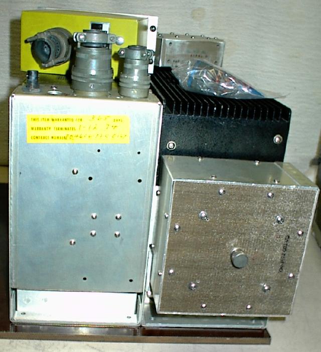
Note the minor changes in the 548S-5 compared to the 548S-3 in the commercial 718 series
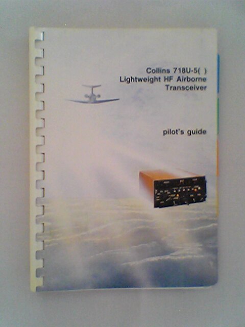
Some information from the user's manual
To offer to help us additional help on this site,
please contact us by sending us a mail at arc-174@cellmail.com!