Updated 7 December 2006 with text
(more to come)

Frequency Range:        2.0000 Mhz to 29.9999 MHz (100 Hz steps)

Channels:               280,000

Modes:                  AM/CW/SSB (LSB/USB  plus A2 [UUSB] and B2 [LLSB])
                        Full 4 channel ISB operation
			Audio Channel is 2.9 KHz wide

                        Voice Attack and delay = 700 to 1300 msec
                        Data capable
				Data 1 = absolute delay of X, AGC attack is <23 msec
				Data 2 = absolute dalay of Y, AGC attack is 80-250 msec, decay of 200-400 msec

Tuning time:            600 msec average, 1500 msec peak (excluding the amplifier or coupler)

Full duplex capable:    Yes	(separate transmit and receive capable)

Split site capable:     Yes 	(this was a common event)

External freq. Std:     Yes

Audio Interface:        600 Ohm, 0 dBm balanced audio (4 wire)	(receive adjustable to -10 to +10)
								(transmit adjustable from -30 to +10)

Receiver RF:            50 Ohm, BNC

Receiver Sensitivity:   .7 uv for 10 dB Signal to noise

Audio rise:             ~1.5 dB with receive levels of 550 uv to .2 Vrms

Exciter RF:             50 Ohn, BNC, 250 Milliwatt (nominal)

Spurious output:        >80 dB down from carrier PEP

Receiver Model:         651H1 or AN/GRR-18

DSP installed:          No

Power Requirement:      120 VAC, 50-450 Hz, 5.0 A, Peak 7.5 A

Cooling:                Unknown (but the manual says it needs a lot of air)

Size:                   Height: 10.4 Inches (26.4 cm)
                        Width:	18.8 Inches (47.8 cm)
                        Depht:	22.6 Inches (57.4 cm)

Remote Control:         Requires two audio channels to support data channels (4800 Hz)
                        One channel of control audio is purely a 4800 Hz "tone" used as a clock
                        The second audio channel for control is a biphase channel for the control data
                        Four (4) full-duplex audio channels to support audio for transmit and receive

Duty Cycle:             Continous operation (100% TX duty cycle)
The URG-II Family is made up with several types of possible configurations:

310Y-1A		Exciter system
651H-1A		Receiver system
651H-2A	 	Receiver system
651H-3A	 	Receiver system
671T-3A	 	Receiver-Exciter system
671T-4A	 	Receiver-Exciter system

Antenna Couplers
409T-3		Coupler
490T-8		Coupler
490X-1		Coupler
409H-1		Coupler Control

Amplifiers
548T-x		Amplifer (see 718 series)	400 Watts
548U-1		Amplifier			1 KW
548U-2		Amplifier			1 KW
648A-1		Amplifier Module		1 KW
648A-1P		Amplifier module		1 KW
208U-3A		Amplifier system		3 KW
208U-10A	Amplifier system 		10 KW

Digital Control
915X-2		Digital Interface Control

Power Supplies
639D-1		Power Supply	50-400 Hz	120/208V	3 Phase
639D-1P		Power Supply    50-400 Hz       120/208V        3 Phase
639D-2		Power Supply    50-400 Hz       120/208V        3 Phase
639D-2P		Power Supply    50-400 Hz       120/208V        3 Phase
636Y-1		Power Supply	400 Hz		115vac		3 Phase
636Y-2		Power Supply    400 Hz		115vac  	3 Phase
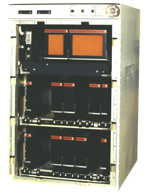
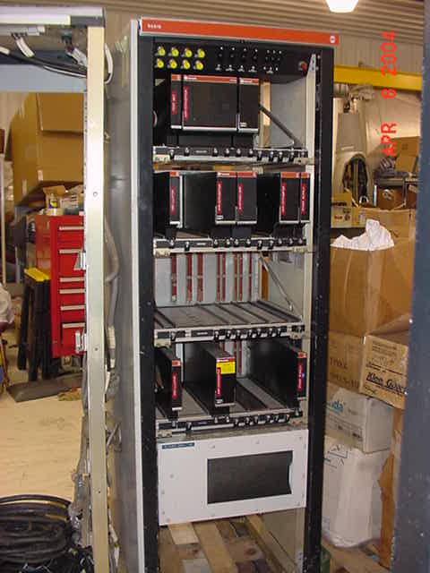
One military configuration is the GRT-17/GRR-18 series. Other variations include the AN/ARC-165 and the AN/ARC-167

Our area of interest is the system is listed below and a quick picture from the AN/TSC-60(V)-2 photo album:
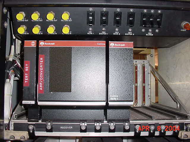
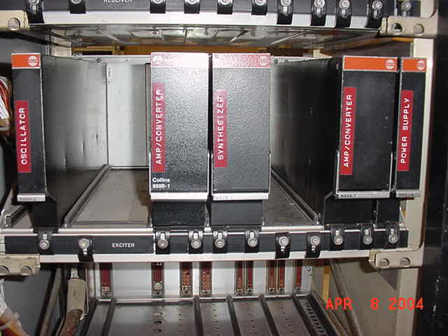
Exciter Shelf (lower unit normally), AN/GRT-17(V)1	CH-644/GRT-17	Collins PN 787-6496-001

Modules installed (left to right)

J1	Shelf cable interface
J2	599H2 	TS-2922
J3		not used
J4	888B-1	Amplifier-Convertor (IF [250 KHz] to RF) 			CV-2649/GRT-17
J5	887B-1	Frequency Synthesizer (acts as DCU)				O-1560/GR
J6		not used
J7		not used
J8	889A-7	Amplifier-convertor (4 channel audio to IF [250 KHz])		CV-2650/GRT-17
J9	889A-7	second connector
J10	652J-4	Power Supply							PP-4922/ARC-132
Receiver Shelf (top shelf normally), AN/GRR-18(V)1	CH-645/GRR-18	Collins PN 787-6495-001

Modules Installed (left to right)

J1	Chalf cable connector
J2	599H-3									TS-2923/GRR-18
J3	888B-2	Amplifier-convertor (RF to IF [250 KHz])			CV-2651/GRR-18
J4	888B-2	second connector (picture of 888B-2)
J5	887B-1	Frequency Synthesizer (picture of 887B-1) (acts as DCU)
J6	889B-1	Audio Frequency Convertor (IF [250 KHz] to audio, A1 and B1)    CV-2652/GRR-18
J7	889B-1	second connector
J8	889A-2	Audio Frequency Convertor (IF [250 KHz] to audio, A2 and B2) 	CV-2653/GRR-18
J9	889A-2	second connector
J10	652J-4	Power Supply							PP-4992/ARC-132
Spares on hand include:

599H-3
652J-2	Power Supply
888B-1	Amplifier-Convertor							790-0940-001
OK-145	Control system for URG-II system

Shelves are also known as Collins 499-R-4

Basic system Documentation is TO 31S1-TSC60-173, Technical Manual, Service, Commuication Center AN/TSC-60(V)1/2/3/4
I have a partial copy dated 1 July 1985 and updated to "change 5"
The actual original date of the document is 15 September 1972

I have about 300 pages to scan and add to the site f anyone needs them.

Modules that are also associated with the URG-II systems include:

789-7497-001   MOD # OK-145/TSC-60(V)   CONTROL MONITOR GROUP
787-6434-001   MOD # TS2915/UCC3(V)     TEST SET, TELETYPE
788-9878-001   MOD # I-1688/TSC-60(V)   AUDIO FREQ MONITOR
787-6445-001   MOD # SB3390/TSC-60(V)  	PANEL, INDICATOR
		975K-1			Test Set	Serial word encoder/decoder
		975K-2			Test Set	Used to test the ATR units in the 208 series Amplifiers
		975K-3			Test Set	Used to test power amplifiers
		974K-4			Test set	Used to test the 208U-3 and U-10 Amplifiers
		975K-5			Test Set	Transportable set for receiver and exciters
		980H-10			Test Set	Used to test the antenna couplers
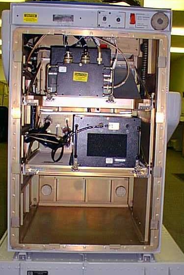
And more data on the URG-II from a URG expert: 888B-1 contains a 3-pole tuneable Bandpass FLTR. For the transmitter function, the filter is used for output of exciter (nominal is 100mw) drive to 648A-1 PWR AMPL. Essentially this reduces output noise to thermal ratio. For the receiver, the filter is in front to provide the rejection of out-of-band adjacent transmitter up to 400Voc, >10% removed from receiver operating frequency (Fc) When I get a chance I'll update/correct your AN/ARC-165 page and send to you. Here is a picture of the 619U-1 cabinet fully loaded.The originally AWACS had a AN/ARC-167, dual AN/ARC-165s. These were upgraded to AN/ARC-194, triple AN/ARC-165 Here is the refit of the AN/ARC-194 "Triple AN/ARC-165s" done for the USAF E-3B/C and UK RAF E-3D. It's called a AN/ARC-229 composed of 3 AN/ARC-230s for USAF and AN/ARC-2200(V) composed of 3 AN/ARC-2201(V)s for the UK
To offer us additional help on this site,
please contact us by sending us a mail at
tsc-60@cellmail.com!