237A Series non Planar Log Periodic Antenna (6.5 to 60 MHz)
	LPA Non Planar
	Different View

	Information to be added
237B-1(2, 3) Rotatable Log Periodic Antenna
	Basic View
	6.5 to 40 MHz
	25 KW average
	50 KW Peak
	15 db Average Front to Back Ratio
	14 db Average gain
	More information to be added
237C Non Planar Log Periodic Antenna - Fixed Direction
	Basic View
	237C-2	4 - 40 MHz
	237C-3	6.5 - 40 MHz
237F-1 Billboard Antenna
	Basic Photo
	Information to be added
237N series Log Periodic monopole Antenna (fixed direction)
	Photo
	Photo 2 (Multiple Arrays)
	Information to be added
237Q-1 Hardened Vertical Antenna (used with the Minute Man Missile Silos) - 110 Ft tall
Information to be added
237Q-2A Hardened Vertical Antenna (used with the Minute Man Missile Silos) - unknown height
Information to be added
237Q-5 Hardened Vertical Antenna (used with the Minute Man Missile Silos) - 28 Ft tall
Information to be added
437C Series Broad Band Vertical Monopole Antenna (3 variations)
	437C-1A 2-20 MHz		108 Feet tall
	437C-2A 2.5-25 MHz		 88 Feet tall
	437C-3A 3-30 MHz		 68 Feet tall
	Rated for 50 KW (average or peak)
	Photo
437G-2A Bidirectional Horizontal Polarized Antenna (2.5 to 30 MHz)
	Photo
	Information to be added
437Y-1A Log Periodic Antenna and Broad Band Vertical Cage Antenna
	Photo
	Information to be added
637B-1 Transportable Log Periodic Antenna
Information to be added
637C-3 Transportable Broad Band Vertical Polarized Antenna
	Photo
	Information to be added
637D-1A Transportable Log Periodic Antenna
Information to be added
637E-1 Fixed Log Periodic Antenna
	Photo
	Information to be added (it does use three towers)
637K-1 Manpack Vertical Antenna (used with the AN/PRC-47)
Information to be added
637P-1/1A Transportable (fixed direction) Log Periodic Antenna (Military AS-2464)
The 637P-1A is a directional HF Antenna for tactical or fixed station use.
It can be operated from 2-30 MHZ with a gain of 7.5 to 12 DB between 4-30 MHz
and below 4 MHz, it has an unidirectional pattern.
The antenna is rated to accept power levels of 10 KW PEP or average.
Model OE-85 (AS-2464) is rated for 3 KW and OE-86 (AS-2465) is rated for 10 KW.
The only difference between the two models is the RF Connector on the balun.
If you desire to upgrade from 3 KW to 10 KW, you can buy the correct connector from a variety of resellors.
Note: if you are using 1/2 LDF-4 (1/2 inch), you will need to replace your cable to at least LDF-5 or to LDF-6.
The LDF-4 is not rated for 10 KW.
10 MHz 11.2 KW
20 MHz 7.8 KW
30 MHz 6.5 KW
LDF-5 ("7/8") is a far more viable choice.
10 MHz 24.0 KW
20 MHz 17.4 KW
30 MHz 13.0 KW
As of June 25, 2021, the average cost for LDF-4 was about $2.75 a foot (not discounted).
The cost for LDF-5 was about $3.50.
The cost for LDF-6 (also known as 1 1/4") is much higher at $7 but note that LDF-6 is now discontinued.
The average VSWR is 2:1 and the Front to Back ratio is 7.5 db to 12 db
depending on several factors.
It is 75' High (on a 80 foot mast) and requires a plot of land that is 310 feet by 200 Feet
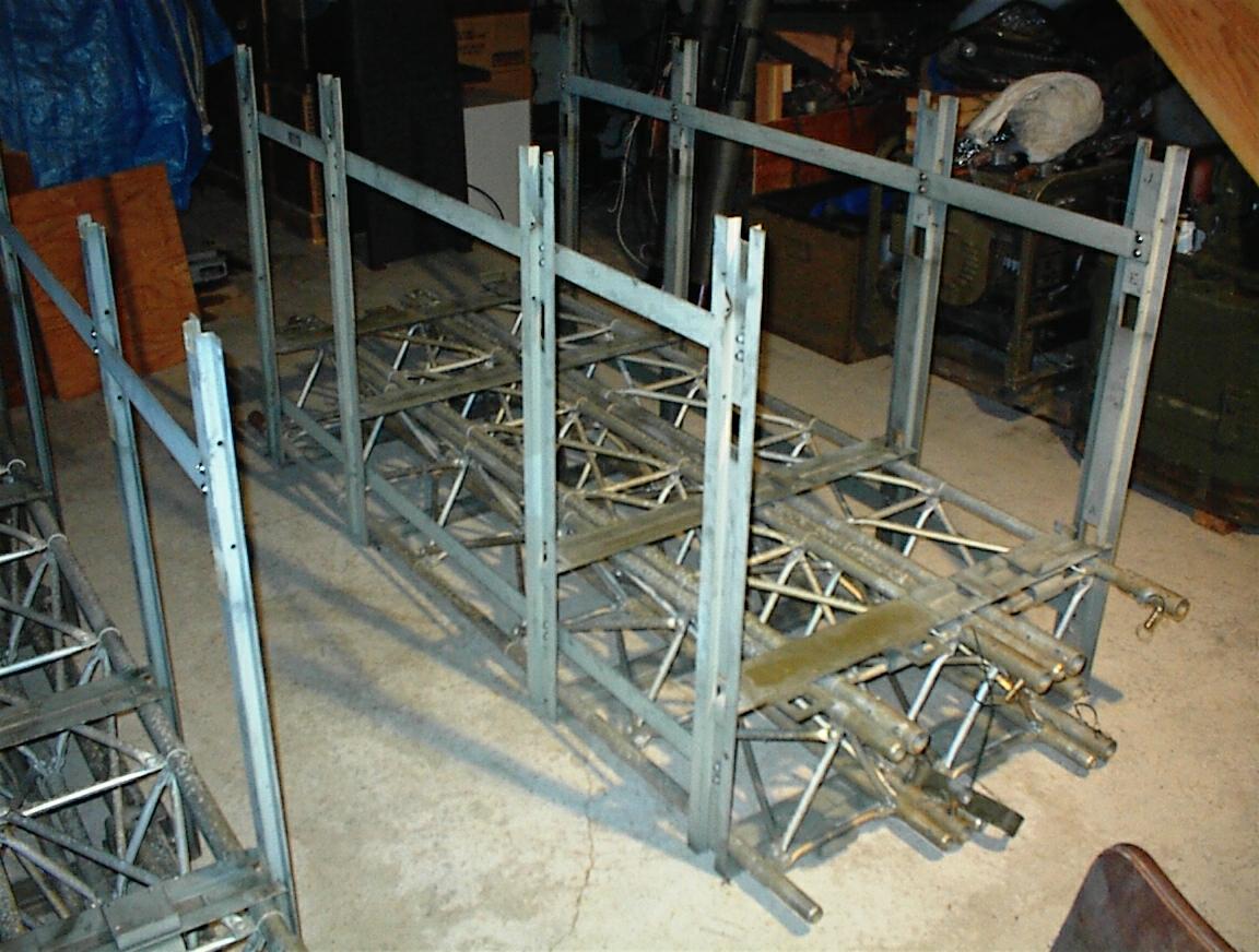
It is designed to be stowed in a frame 57" x 35.5 " x 92" and can transported by truck or air.
It weighs 1270 lbs. We keep ours on two furniture dollies. The cable reels and coax are not part of the 1270 pounds.
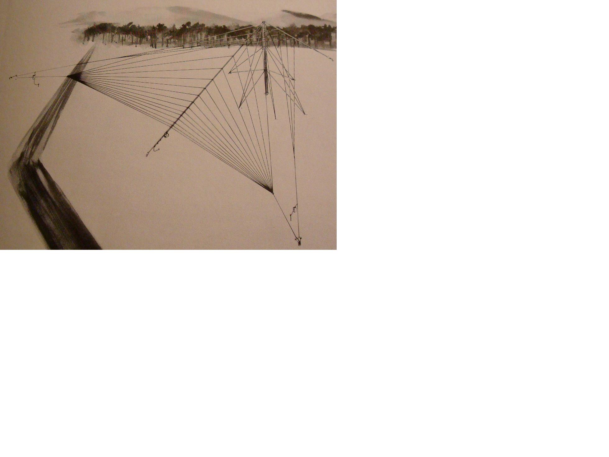
Installattion
=============
A 80" portable tower is erected and guyed at three levels.
The curtain array is attached to the top of the tower and is stretched
forward 100 feet to the ground while a counter wire goes the opposite
direction to the ground out 100 feet. The extention to the front has a
wire array going out in either side to out posts that are 300 feet
apart forming a huge triangle back to the top of the tower.
See this drawing
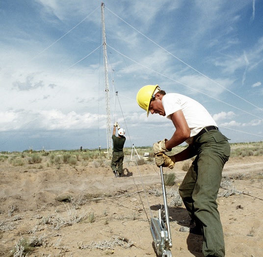
Photo 1
Installation of the tower
According to the manual, it will take a five man crew about 1 hours to install and test the
antenna on a typical flat field. (We assume they are well trained!)
In discussions with actual people who have installed this antenna, it is more like 6-8 hours and with 4-5 people.
In addition, the same people have indicated that "text book" installation provides for pattern that is for up to a medium length path.
The antenna installation can be modified to provide for medium to long path usage by lifting the curtain ends by 20-30 feet.
This changes the angle of tilt to the horizon to something about 10 degrees from about 30-35 degrees.
If your intent is having reliable communications over a 2-4,000 mile path, you need to elevate the curtain to lower the take-off angle.
If you plan to work a longer path and also have a high confidence level, you should raise the curtain edges as high as you can get them.
Having a take-off angle of less than 10 degrees should be a target and having one of less than 5 degrees is ideal.
However, the path must be studied to really understand the receive angles (due to more than one hop that may be involved)
and a clear understanding that time of day and the day of the year greatly influence path engineering.
You should consider using a magnetic loop receive antenna array at the receive site to greatly improve path reliablity.
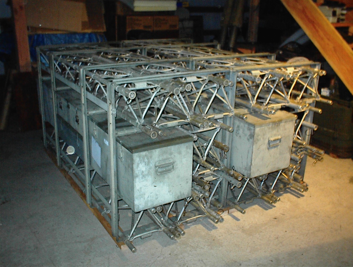
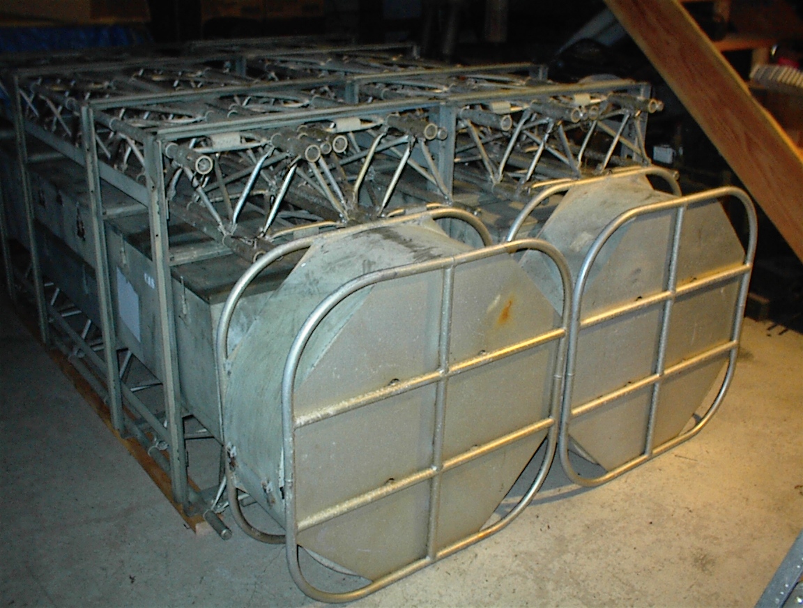
Images of it in the storage system:
basic pack frame
Two 637's in storage (1)
Two 637's in storage (2)
637X-1 Orthogonal antenna - part of the AN/TSC-60(V) series shelter systems
	AS-2482 - This is an interesting antenna for receive use.
        Information to be added (there has also been one on eBay!)